
Global Site> Electrical Evaluation System > SGA-25 Subgap Optical Absorption Measurement System
SGA-25 Subgap Optical Absorption Measurement System
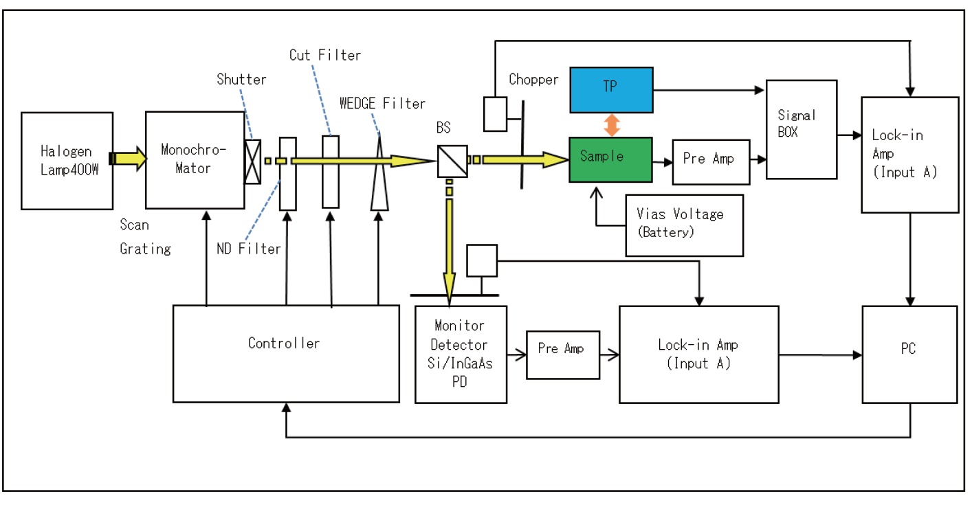
With using the constant photocurrent method(CPM method),this system can measures the weak defect light absorption of a semiconductor thin film that cannot be detected by general transmission spectroscopy. The system is ideal for evaluating the defect density and defect level of amorphous silicon and oxide semiconductors. The measurement principle is to irradiate the sample with monochromatic light and control the light intensity so that the photocurrent is constant at each wavelength. The irradiation light intensity value is monitored by the built-in monitor detector. The absorption coefficient is caluculated from the irradiation light intensity value.
|
|
| Catalog(PDF) |
Features
- An ideal instrument to evaluate defect level of oxide semiconductors such as In-Ga-Zn-O(IGZO)
- For measurement range, two systems are available ; one to cover the range from 500~2100nm(0.59~2.48eV) and another to cover the range from 300~1200nm (1.03~4.13eV)
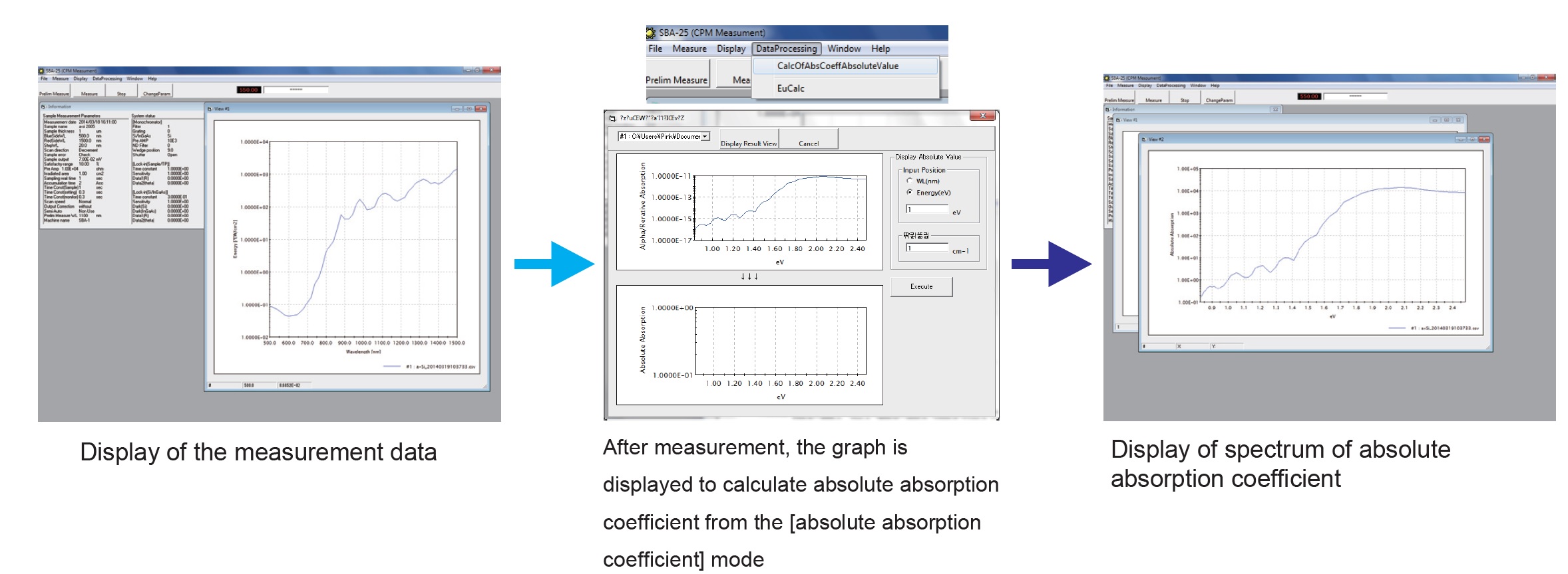
Diagram of measurement procedure
 |
Measurement data of amorphous silicon(example)
|
|
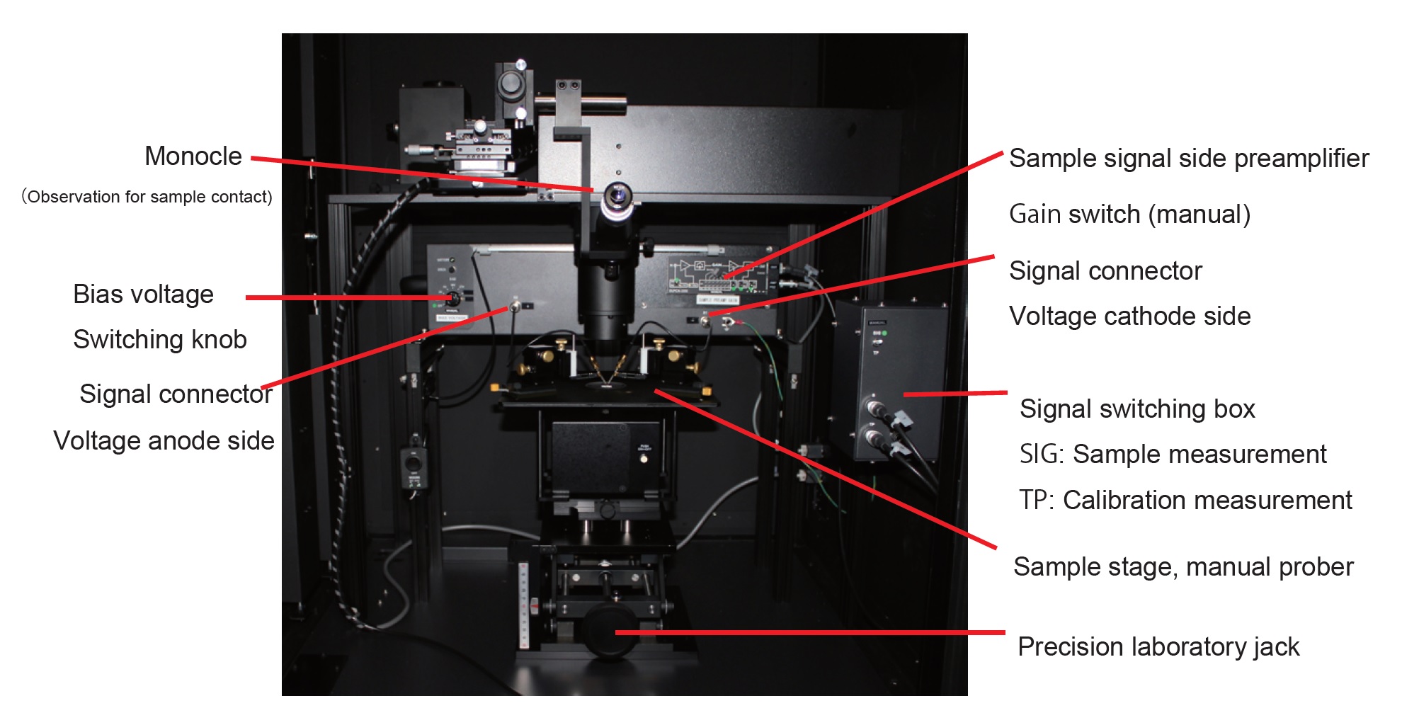
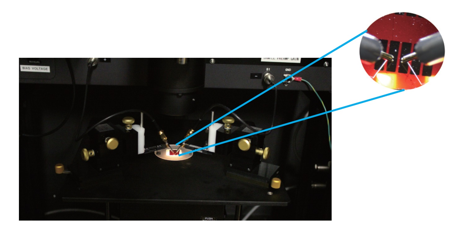
Sample compartment and sample contant
|
|
|
Specifications
| Measurement method |
Constant photocurrrent method(CPM method) |
| Wavelength range(Halogen type) | 500~2100nm(0.59~2.48eV) |
| Wavelength range(Xenon type) | 300~1200nm(1.03~4.13eV) |
| Irrdiation area | Exchange of the lens for 10×10mm(Entire irrdiation area 14×14mm)and 6×6mm |
| Non uniformity in iradiation area | Within ±10% |
| Light intensity stability | Within ±5% |
| Variable range of irrdiation intensity | 100nW/cm2~5mW/cm2 (at 550nm) |
| Wavelength purity |
Approx.24nm(with 4mm slit width of monochromator) |
| Wavelength accuracy | ±0.2nm |
| ND filter | 5pcs(10% 1% 0.1% 0.01% 0.001%) |
| Exit light | DC or chopped light,menually switching |
| Variable chopper | Variable frequency range DC/0.1~100Hz |
| Sample |
Size 10×10mm (For other size, optional sample stage and etc. can be offered) |
| Sample current measurement method | Connect a current amplifier to sample and measure output voltage with a look-in amplifer |
| Minimun detection current | 100fA |
| Absorption coefficient measurement range | 6 digits |
| Bias power supply | 1.5V・3V・9V・18V・27V with the use of dry batteris |
| Sample observation | Monocle, camera, monitor display(Field of vies 2.0×1.5~16×12mm) |
Configurations
●Halogen lamp 400W(the system is for Halogen type)
●Halogen lamp 400W PS(the system is for Halogen type)
●Optical system for condensing light source
●Monochromator
●Grating, 600 lines/mm, 300nm blaze
●Grating, 600 lines/mm, 1600nm blaze
●Exit opticak light condensing unit(Auto variable and continuous ND filter)
●Variable frequency chopper, DC/0.1~100Hz
●Different type of Higher-order cut filter
●Sample compartment
●Lockin Amp for light intensity monitor
●Lockin Amp for sample current measurement
●Si photo diode detector
●TP unit
●Sample stage, manual prober, Precision laboratory jack
●Bias power supplay
●Monocle, camera, monitor display
●software
●Interface unit
●Desktop PC
●Instruction Manual
Dimensions
●Operation:AC100V ±10V 50/60Hz 10A(220V or other voltage is possible with the dedicated transformer for oversea operation)
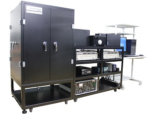
●Main unit:Approx.W1850×D700×H1400mm
●Weight:Approx.400Kg
Related Product
BIP-KV100 Ionization Energy Measurement System
 |
|
LBC-2 Laser Induced Current Measurement System
 |
|
